8.3. LAYER Object#
LAYER begins with identification as a layer and ends with END. This
section describes how to publish a layer to a map. There should be at
least one layer in the MapFile file, which is used to produce maps.
MapFilezhong layers are displayed in reverse order on the map (the first
layer is at the bottom and the last layer is at the top).
8.3.1. General introduction to LAYER object#
3.1.1 General Layer Setting#
NAME: the short name of the layer, which should be less than 20 characters. This name is the channel between the Mapfile and Web interfaces. The layer name should be unique, otherwise one layer will be replaced by another. You can use the GROUP option to associate a set of layers. ~ value: ~[name]
GROUP: the group name to which the layer belongs. The group name can be referenced by a template file. You can control the ON and OFF of a set of layers by the group name. Value:[name].
METADATA:13) METADATA: use this identity to store arbitrary key-value pairs. It is often used when configuring OGCWMS. When creating a template, it is also very flexible, as entered here Any content can be obtained through template changes. Example:
METADATA title “Map of China” autor “YanMing” END
STATUS: sets the state of the layer. It is generally controlled by MapServer itself and defaults to ON. Value:
[on|off|default]TYPE: sets the performance type of the data. The data does not have to be of type shapefile. For example, shapefile of polygon type can be rendered using point However, a shapefile file of type point cannot be rendered with polygon. Generally speaking, ANNOTATION means adding a realistic LABEL to the layer The layer itself is not displayed (although you can do so). The LABEL of the point is displayed at the location of the point. The LABEL of the face is displayed in the centroid position of the face. if the centroid is not in the face, the LABEL will be displayed in the area closest to the centroid. The LABEL reality of the line is visible in the middle of the line. QUERY means that the layer can be queried but not displayed. When distinguishing between the opposite side and the line, be sure to mainly fill the color setting, when rendering the opposite side. If the filling color is the same as the background color, then all you see is the boundary of a face. When using CIRCLE, you must define the extents of its minimum Bounding rectangle.
Value:[point | line | polygon | circle | annotation | raster | query]
MINSCALE: the minimum scale of the layer. Value: [double]
MAXSCALE: the maximum scale of the layer. Value: [double]
SYMBOLSCALE:The scale at which symbols and/or text appear full size. Value: [double]
TRANSPARENTCY: sets the transparency of the layer. 0 is transparent and 100 is opaque. Value: [integer | alpha].
OFFSITE: the color index (Sets the color index to treat as transparent for raster layersb) of the grid layer. Value:[r] [g] [b]
POSTLABELCACHE: tell MapServer to render the legend after all the labels have been rendered. It is useful when adding elements of the same kind. The default is false. Value: [true | false]
CLASSITEM:Item name in attribute table to use for CLASS lookups. Specifies the name of the property to query. Value: [attribute]
Example:
# ----------------------------------------------------------------
# Layer Danger Zones
# ----------------------------------------------------------------
LAYER
NAME  "Danger Zones"
GROUP "Zoning" METADATA   title  "Danger Zones"
  author "Department of Environment Protection"
END
TYPE POLYGON
MINSCALE 0
MAXSCALE 1000000
SYMBOLSCALE 1000
STATUS ON
TRANSPARENCY 50
...
3.1.2 Data Settings#
3.1.2.1 Shapefiles#
Data in Shapefile format is the most widely used data in MapServer.
^ 1) ^ DATA shapefile The name and path of the file without an extension. The path can be absolute or relative to ~ SHAPEPATH The path of. Value: [path/filename].
Example:
DATA “data/hangzhou”
3.1.2.2 Connect to OGR#
CONNECTIONTYPE:OGR
CONNECTION:OGR Supported data source name ~. For file-based data sources, it is necessary to define the name, path and extension of the file, which can be absolute or relative path, relative path is the path relative to SHAPEPATH, if SHAPEPATH is not set, the path relative to the directory where the .map file is located; for directory-based data sources, the value is
The path to the corresponding directory. ~ value ~:[datasource_ name]
the value of DATA:[layer_ definition] ~ is the name or number used by the data source or ~ SQL String, etc. ~ take ~ value:[layer_ definition]
STYLEITEM AUTO: it specifies that the original dataset will be used STYLES . But if the original number
According to the STYLE type that MAPSERVER does not support, ~ may be ignored or error. ~
Example 1:-MapInfo File; displays a MapInfo TAB file in its source colors Using STYLEITEM AUTO:
LAYER
NAME "Built-up Areas"
TYPE POLYGON
CONNECTIONTYPE OGR
CONNECTION "data/tab/builtup\_areas.tab"
STATUS ON
STYLEITEM AUTO
  CLASS
    NAME "Built-up Areas"
  END
END
Example 2:DGN File; displays layer “0” (DGN terminology = Level) from a DGN-File in a light blue:
LAYER NAME "Water"
TYPE POLYGON
CONNECTIONTYPE OGR
CONNECTION "data/dgn/wat.dgn"
DATA "0"
STATUS ON
  CLASS
    NAME "Water"
    COLOR 0 200 255
  END
END
3.1.2.3 Connect to Databases#
3.1.2.3.1 SDE
CONNECTIONTYPE sde
The connection string “DATA” of the CONNECTION “sde database” contains Geometry Layer name of the field “
Example:
CONNECTIONTYPE sde
CONNECTION "myhost,esri\_sde,gisdb,userid,password"
DATA sites.shape
3.1.2.3.2 POSTGIS
CONNECTIONTYPE postgis
CONNECTION “connection string for postgis database”
The format of the DATA value is & lt; column name & gt; from & lt; table name & gt;, column name contains geometry And the table name is the table name of the corresponding data Example:
CONNECTIONTYPE postgis
CONNECTION "user=gis_user dbname=gis host=localhost" >
DATA "the_geom from s81"
3.1.2.3.3 ORACLE
CONNECTIONTYPE oraclespatial
The connection string for the CONNECTION “oracle database, such as
user/pass[@db]
The format of the DATA value is & lt; column name & gt; from & lt; table name & gt;, column name contains geometry, and the table name is the table name of the corresponding data.
Example:
CONNECTIONTYPE oraclespatial
CONNECTION <%22spa/sig@spa>"
DATA "GEOLOC from FP10010\_LINES"
3.1.2.4 Web Map Service (WMS)#
Use WMS as the data source.
CONNECTIONTYPE WMS
OnlineResource URL of the CONNECTION WMS server. URL without any parameters. Value: [url]
METADATA (required): metadata information must be obtained: wms_ srs Space-delimited EPSG coordinate code wms_ name comma-separated WMS layer name
Wms_ server_ version WMS service version number wms_ format
The image format METADATA (optional) used in the GetMap request can be found in the configuration document corresponding to WMS.
wms\_connectiontimeout wms\_latlonboundingbox wms\_style
Wms _ & lt;stylename> _ sld
wms\_time

wms\_force\_separate\_request
Example:
LAYER
NAME "prov_bound"
TYPE RASTER
STATUS ON
CONNECTION "<a href="http://www2.dmsolutions.ca/cgi-bin/mswms_gmap" target="_blank">http://www2.dmsolutions.ca/cgi-bin/mswms_gmap)?</a>"
CONNECTIONTYPE WMS
  METADATA
    "wms_srs" "EPSG:42304 EPSG:42101 EPSG:4269 EPSG:4326 EPSG:42304"
    "wms_name" "prov_bound"
    "wms_server_version" "1.1.0"
    "wms_formatlist" "image/gif,image/png,image/jpeg,image/wbmp"
    "wms_format" "image/gif"
  END
END
3.1.3 Symbol specific Settings#
TOLERANCE: the sensitivity of queries based on points or lines. ~ if ~ TOLERANCEUNITS Is the default, then the default value for TOLERANCE is 3px. If you want to restrict queries of type polygon, you need
To set the value of TOLERANCE to 0. Value:[double]
TOLERANCEUNITS: unit of TOLERANCE, which defaults to pixels. Value:
3.1.4 Tiles#
fully qualified name of the location or index of the tile of the TILEINDEX:~ layer (~ Full filename for The index or tile definition for this layer). And ArcInfo The index of the library is similar to this shapefile
The file contains the polygon characteristics of each tile. TILEITEM gives the location message of the tile data.
Interest. If the DATA parameter is not empty, its value is added to the end of the position. If DATA Is empty, this location contains the fully qualified name of the file. Note: DBF of SHAPEFILE The file contains a tile index, but its name must be the same as that used in Mapserver, so that Mapserver can correctly index the corresponding tile data.
TILEINDEX files can be created automatically using the GDALTINDEX tool.
TILEITEM:~ contains the field name of the tile path. The default is “~ LOCATION”. Value:[attribute] Example:
#—————————————- # Raster Tiles # White set to transparent [OFFSITE] #—————————————- LAYER NAME “Raster Maps” TYPE RASTER MINSCALE 0 MAXSCALE 50000 STATUS ON TILEINDEX ‘raster_tiles’ OFFSITE 255 255 255 END
3.1.5 Filter Option#
FILTER: filter the attributes of the data and select the data under the specified condition. Value:[string] Example: FILTER “type=‘road’ and size & lt;2”
Fields used in FILTERITEM:FILTER expressions, for OGR and SHAPEFILE only It works. Value:[attribute]
Example: ~ use ~ FILTER and CLASSITEM to control fonts and colors
#-----------------------------------------------
# Sewer Annotation Layer 1
#-----------------------------------------------
LAYER
NAME "Sewer, normal Text"
TYPE ANNOTATION
MAXSCALE 600
STATUS ON
CONNECTIONTYPE OGR
CONNECTION "LK/Texte_MI.TAB"
LABELITEM "OGR:LabelText"
LABELANGLEITEM "OGR:LabelAngle"
LABELSIZEITEM "label_size"
POSTLABELCACHE true
SIZEUNITS inches
CLASSITEM igds_color
FILTERITEM igds_font
FILTER "24"
  CLASS
    EXPRESSION "4"
    LABEL
      ANTIALIAS TRUE
      TYPE TRUETYPE
      FONT arial
      COLOR 0 170 255
      POSITION ur
    END
END
  CLASS
    EXPRESSION "40"
    LABEL
      ANTIALIAS TRUE
      TYPE TRUETYPE
      FONT arial
      COLOR 80 80 80
      POSITION ur
    END
  END
PROJECTION
 "init=world:CH1903"
END END
3.1.6 Label Option#
You can refer to the relevant contents of LABEL OBJECT.
LABEL ITEM: the field name in the property sheet. Value: [attribute]
The minimum scale displayed by LABELMINSCALE:LABEL. ~ value: ~ [double]
LABELMAXSCALE: the maximum scale displayed by LABEL. ~ value: ~ [double]
LABELCACHE: specifies whether it is cached and displayed after the layer is rendered. The default is on. Value: [on | off]
LABELREQUIRES::~ displays the context (condition) of ~ LABEL display. Such as LABELREQUIRES ( [Orthoquads] != 1) Under this condition, if the orthoquads graph
LABEL is not displayed when the status of the layer is ON. The expression must be a STATUS-based#
BOOLEAN expression, use logic to manipulate AND or OR. Value:
[express]
Example:
LAYER
NAME "Percels"
TYPE POLYGON
STATUS ON
DATA "geo/shape/percels.shp"
MINSCALE 0
MAXSCALE 2000
LABELITEM PARCELNUM
LABELANGLEITEM ANGLE
  CLASS
    COLOR -1 0 0
    OUTLINECOLOR 192 192 192
      LABEL
        TYPE truetype
        FONT "arial"
        SIZE 7
        COLOR 0 0 200
       POSITION auto
     END
  END
END
3.1.7 Other options#
DEBUG: ~ debugging is allowed. The detailed results of debugging are put in ~ STDERR (the standard) Error output), if the LOG parameter is used in Web Object, put it in MapServer In logfile file.
DUMP: ~ confirm whether ~ MS can return data in GML format. When using WMS
The GetFeatureInfo option is useful, and the default is false.
the template file used by HEADER:~ is only used for ~ Multiresult query modes.
the ~ Footer template file used by FOOTER:~ is only valid in Multiresult query mode.
MAXFEATURES: specifies the maximum number of features to draw this layer in the current window.
PROCESSING: sends processing instructions to the layer. Different types of layers and programs that process instructions support different instructions. Current raster image support (handled by GDAL): SCALE,BANDS,
COLOR _ MATCH _ THRESHOLD and DITHER. For example:
PROCESSING "SCALE_1=AUTO"
PROCESSING "SCALE_2=AUTO"
PROCESSING "SCALE_3=AUTO"
PROCESSING "BANDS=3,2,1,4"
Example:
Resampling: Producing map output from raster images not Using its original resolution results in blurred results. To avoid that You should use resampling. Be aware to use 24bit output in this case (best is JPEG). Options are AVERAGE, BILINEAR and CUBIC. See as well http://mapserver.gis.umn.edu/development/rfc/ms-rfc-4)[.](http://mapserver.gis.umn.edu/development/rfc/ms-rfc-4
PROCESSING “RESAMPLE=AVERAGE”
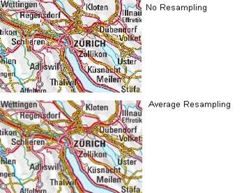
image7#
Dither turns on error diffusion mode, used to convert 24bit Images to 8bit with error diffusion to get better color results when Outputting to 256 color images (8 bit, such as PNG and GIF):
PROCESSING “DITHER=YES”
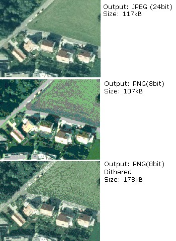
image8#
An image would often use up all 256 color entries. The Following processing is a way to avoid “stealing” your whole colormap For a raster layer. Normally values in the range 2-6 will give good Results:
PROCESSING “COLOR _ MATCH _ THRESHOLD=n”
REQUIRES:~ sets whether the layer tag is displayed. Such as: ~
ABELREQUIRES () [Orthoquads] != 1) It means that if there is a place called “orthoquads”
In the active state, the layer cannot be marked. The expression (Expression) is a boolen Expression,[layer name] = 1 if the Status of a layer is on, otherwise
[layer name] =0。
SIZEUNITS:~ sets the unit of the Class object to pixels by default. Yes, simulating. Buffering is valid. ~ value: ~[pixels | feet | inches | kilometers | meters | miles].
TEMPLATE:~ serves as a global replacement for ~ CLASS TEMPLATE. ~ value: ~[file | Url]
TRANSFORM: Determines whether a layer needs to be transformed from a geographic coordinate system to an image coordinate system. Defaults to true. This parameter allows creating shapefiles as image coordinate systems. So some features are always shown in the same position in the same image. It should be noted that the coordinate origin of the image coordinate system is in the upper left corner, the positive x-axis is to the right, and the positive y-axis is downward. Value: [true|false]
8.3.2. 3.2 CLASS Object#
Use CLASS to specify the corresponding theme for the layer
the name of NAME:CLASS ~. Value: ~[name]
EXPRESSION: compare string with ClassItem to determine Class. There are three expressions:
Strings, regular expressions, logical expressions. If no string is given, then all the features
The collection all belong to this Class. Strings are case-sensitive and easy to process quickly. There are no escape characters. Regular expressions need to be defined with / regex/. There is no need to quote. Logical expressions allow you to build fairly complex tests based on one or more attributes, so only for the shapefile file is valid. Logical expressions are defined in the form “(expression)”. Use the attribute to be added with[], that is, “[ATTRIBUTE]”. Note that attribute values are case-sensitive and should be associated with In the shapefile file
The fields are consistent.
For example: EXPRESSION ([POPULATION] & gt; 50000 AND’[LANGUAGE]’eq
‘FRENCH’)
Logical expression ~ allow operator: ~ =, & gt;,<,<=,>=,=,or,lt,gt,ge,le,eq Its processing speed is slower. Both strings and regular expressions are classified according to classitem in layer. Same layer You can have a class that uses all three expressions at the same time.
Value:[string]
COLOR: the color of the drawing feature. ~ value: ~[r] [g] [b]
OUTLINECOLOR: the color of the outline of the polygon symbol, ~ polyline is not supported. Value:[r] [g] [b]
BACKGROUNDCOLOR: the color of the opaque area. Value:[r] [g] [b]
SYMBOL: sets the symbol used. Symbol used when the property sheet is not set When the name or numeric value of the The numeric value is the index of a symbol in the symbol file, starting with 1. You can also use NAME to make the symbol file with the corresponding symbol . ~ default is ~ 0, which means: a single pixel,single width line, or solid Polygon fill, depending on the layer type. Value:[integer | string].
SIZE: the height of the symbol, in pixel. Only scale symbols are used. The default is one.
MINSIZE: the minimum size of the drawn symbol, in pixel. The default is 0 . Value:[integer]
MAXSIZE: the maximum size of the drawing symbol in ~ pixels. The default is ~ 50. Value:[integer]
SYMBOLSCALE: the scale at which text or symbols are displayed. Allow layers to follow map The proportion of changes in dynamic size. If it is not set, the size of the layer will never change. Vs. MINSIZE is related to MAXSIZE. Value: ~[double].
TEXT: label displays the static text of ~. It can be compared to ~ LABELITEM. A better result. Make
Use () as the delimiter. It allows you to integrate multiple attributes into a single label. For example:
([FIRSTNAME],[LASTNAME]) . Value:[string]
TEMPLATE: a template file used to represent query results. It is usually an htm file. Value:
[filename]
DEBUG: debugging is allowed. The detailed results of debugging are placed in STDERR (the standard error) Output), if the LOG parameter is used in Web Object, put it in MapServer logfile In the document. Example:
# —————————————————————- # Layer Parcel Corner Points # The symbol and the size are assigned depending on the # database column “TYPE” # —————————————————————-
NAME “Parcel Limit Points” TYPE POINT MINSCALE 0 MAXSCALE 2000 SYMBOLSCALE 1000 STATUS ON CONNECTIONTYPE OGR CONNECTION “..dataparcel_limit_points.TAB” CLASSITEM “TYPE” CLASS NAME “Stone” EXPRESSION “Stone” COLOR 255 255 255 SYMBOL ‘circle’ SIZE 3 END CLASS NAME “Iron” EXPRESSION “Iron” COLOR 255 255 255 SYMBOL ‘circle’ SIZE 2 END CLASS NAME “Cross” EXPRESSION “Cross” COLOR 255 255 255 SYMBOL ‘cross’ SIZE 2 END END
Results:
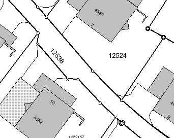
image9#
Overlaying Symbols
One symbol can be superimposed on another as a description of the symbol, and so on. The following parameters can
Define overlay symbols, which are used the same as non-overlay symbols:
OVERLAYBACKGROUNDCOLOR
OVERLAYCOLOR
OVERLAYOUTLINECOLOR
OVERLAYSIZE
OVERLAYMINSIZE
OVERLAYMAXSIZE
OVERLAYSYMBOL
2.1.1 LABEL Object#
Use LABEL correspondence to define a label, which is used to describe a feature of the layer. It can be set using TrueType fonts when LABEL is defined. Use LABELITEM to add labels to features.
This object is used to define a label, which is in turn usually used to annotate a feature with a piece of text. Labels can however also be used as symbols through the use of various TrueType fonts. Features are labeled using the Http://umn.mapserver.ch/MapServer/en/layer.htm#LABELITEM)[.](http://umn.mapserver.ch/MapServer/en/layer.htm#LABELITEM
2.1.1.1 Basic Settings#
the font type used by TYPE:~, ~ bitmap is more efficient than truetype, but truetype Type font update is more convenient. Value:[bitmap | truetype]
the name of the FONT:~ font (reference ~ FONTSET). Value:[name]
the color of COLOR:~ text. Value: ~[r] [g] [b]
SIZE: text size. The size corresponding to the substitute defined in SIZEUNITS. Correspondence The value of TrueType[integer | layer column]
The corresponding value of bitmap[tiny | small | medium | large | giant]
ENCODING: displays the encoding of characters, such as Japaneses . If the value provided is not supported, the corresponding LABEL Will not be displayed. ~ value: ~[string]
PRIORITY:~ sets the priority of ~ LABEL. Value:[integer]
the minimum display size of MINSIZE:~ fonts. The default is ~ 4. Value:[integer].
maximum display size of MAXSIZE:~ fonts. The default is ~ 256. Value:[double]
the minimum size of the marked feature of MINFEATURESIZE:~, in ~ pixels units, only for Cached labels is valid. The alignment data is the length. Is the smallest area for polygons. If you select “Auto”, MapServer displays only tags with features that are much larger than their tags. Value:[integer|auto]
2.1.1.2 Text Effects#
Whether ANTIALTAS:~ uses anti-aliasing (smoothing). Value: ~ [true | false].
OUTLINECOLOR: the color of the text boundary, which defaults to no boundary. Value: [r] [g] [b]
SHADOWCOLOR:~ text shadow color. Value: ~ [r] [g] [b]
SHADOWSIZE:~ text shadow size. Value: ~ [x] [y]
BACKGROUNDCOLOR:~ background color. Default is ~ OFF. ~ value: ~ [r] [g] [b]
BACKGROUNDSHADOWCOLOR:~ background shadow color. Default is ~ OFF. Value: [r] [g] [b]
BACKGROUNDSHADOWSIZE:~ background shadow size, default is ~ 1. Value: [X] [y]
2.1.1.3 Position Option#
the location of POSITION:Label. The first letter is the “Y” position and the second is the “X” position. “Auto”tells MapServer to calculate the location of the label that will not conflict with other label. Value: [ul | uc | ur | cl | cc | cr | ll | lc | lr | auto]
ANGEL: the value is expressed in the angle system. Indicates the angle of the label. You can use AUTO for line layers Value, you can specify the corresponding exact angle, such as: ANGLE [Rotation]. Value: [double | auto | follow | attribute]
the offset of OFFSET:LABEL, in ~ pixels, relative to the position of the upper left corner.
MINDISTANCE:~ copies the label generated by a ~ label and the copied label The minimum distance between. Unit pixels. ~ value: ~ [integer].
BUFFER: in LABEL Fill the surrounding with the appropriate color, can improve the readability of the text, the default is 0. Value: [integer]
FORCE:~ forces the use of the corresponding CLASS for ~ LABEL, regardless of whether it is associated with another LABEL or not Conflict, valid only for cached label. The default is false. Value: [true | false].
whether PARTIALS:~ displays incomplete ~ LABEL, no partial coordinates are displayed by default. Value: [true | false]
WRAP:~ represents the character at the end of the line. Value ~: [character]. Example:
# —————————————————————- # Layer Object Names # The names are rotated along the lines # —————————————————————-
LAYER NAME “Object Names” STATUS ON TYPE LINE MINSCALE 0 MAXSCALE 1000 SYMBOLSCALE 500 DATA “landcover/object_names” LABELITEM “NAME” CLASS LABEL TYPE TRUETYPE FONT Arial SIZE [sizeitem] COLOR 0 0 0 OUTLINECOLOR 255 255 255 ANTIALIAS TRUE ANGLE [angleitem] FORCE false END END END
2.1.2 STYLE Object#
Symbolization can be achieved using STYLE. You can use multiple STYLE for a layer.
COLOR: the color of the drawing feature. Value:[r] [g] [b]
OUTLINECOLOR: the color of the outline of a polygon symbol. Linear symbols are not supported. Value:[r] [g] [b]
the color of BACKGROUNDCOLOR:~ opaque symbols. Value: ~[r][g][b]
SYMBOL: sets the symbol used. Symbol used when the property sheet is not set When the name or numeric value of the The numeric value is the index of a symbol in the symbol file, starting with
You can also use NAME to make the symbol file with the corresponding symbol. The default is 0, which means: a single pixel,single width line, or solid polygon Fill, depending on the layer type. Value:[integer | string].
ANTIALIAS: whether or not to TrueType Fonts use a smooth (anti-aliasing) effect. Value:[true | false]
SIZE:~ uses the symbol size value in units of ~ SIZEUNITS. The default value is 1, only for Scalable symbols is valid. Value:[integer]
The field name of the SIZEITEM:~ storage size in ~ SIZEUNITS. Value:[String]。 8) The minimum value of the symbol drawn by MINSIZE:~ in ~ SIZEUNITS. Value:[double]
the maximum value of symbols drawn by MAXSIZE:~, in ~ SIZEUNITS. Value:[double]
OFFSET:~ voids and shadows ~
the angle of the ANGLE:~ line, for ~ HATCH Type, shadow line ~, in degrees. Value: ~[double]
ANGLEITEM: the name of the field in which the angle value is stored, with a value of 0 Indicates that there is no rotation. Value:[double]
the width of the WIDTH:~ line, default is ~ 1. Value:[integer]
MINWIDTH:~ uses ~ HATCH The minimum width of the ~ line of the symbol of type. Value: ~[integer]
the maximum width of lines that MAXWIDTH:~ uses symbols of type ~ HATCH. Value:[integer]
Example 1:Streets signature using overlaying lines in two thicknesses and Coloers LAYER
NAME “Motorwway”
TYPE LINE
MINSCALE 23500
MAXSCALE 140000
STATUS ON
LABELITEM “NAME”
DATA teleatlas/streets/streets_ main_ roads_ polyline
CLASS
STYLE

  SYMBOL "continue"

  SIZE 4

  COLOR 255 0 0
END
STYLE
SYMBOL "continue"

SIZE 2

COLOR 255 240 12
END
END
END Example 2:Hatching
Symbol definition in Symbol File:
SYMBOL
NAME ‘hatch-test’
TYPE HATCH
END
Layer definition in Mapfile:
LAYER…
CLASS…
STYLE

  SYMBOL 'hatch-test'

  COLOR 255 0 0

  ANGLE 45

  SIZE 10

  WIDTH 3

END
END
END
8.3.3. 3.3 JOIN Object#
Defines how to handle JOIN,JOIN defined under the QUERY pair.
A unique name for the NAME:JOIN. Value:[string]
XBase for TABLE:~ to perform ~ JOIN operation File name (DBF, containing the name of the path). Value:[filename]
FROM:Join item in the shapefile. Value:[item]
TO:Join item in the table to be joined. Value:[item]
types of TYPE:JOIN. The default is singel. Value:[single | multiple]
TEMPLATE:~ in ~ one-to-many The name of the template file in the case. The template file is called every time a record is processed and can only be replaced by JOIN Items in TABLE. Value:[filename].
Example: In the following example we join the layer parcels to a table Owners using columns NUMBER in Parcel and PARCEL_ NR in Owners as key Fields:
LAYER
NAME “Parcels”
STATUS ON
DATA “data/parcels”
TYPE LINE
HEADER “NUMBER AREA NAME ZIP LOCALITY”
JOIN
NAME “Owners”
TABLE “data/owners.dbf”
FROM NUMBER
TO PARCEL _ NR
TYPE multiple
TEMPLATE owners.htm
END
CLASS
COLOR 0 0 0
SYMBOL “continue”
SIZE 2
TEMPLATE parcels.htm
END
END
8.3.4. 3.4 PROJECTION Object#
Tip: if the projection of your data is consistent, you generally do not need to set the projection.
If you want to set the projection, generally we have to set two kinds of projection, the output projection and the input projection. Output input
The shadow is the projection corresponding to MAP, which is set under MAP; the input projection value refers to the projection of each LAYER.
The PROJECTION object consists of a series of PROJ.4 keywords. Here is an example:
PROJECTION
  "proj=utm"
  "ellps=GRS80"
  "zone=15"
  "north"
  "no_defs"
END
Geographical coordinates are defined as follows:
PROJECTION
  "proj=latlong"
END
The coordinate parameters for using EPSG are as follows:
PROJECTION
  "init=epsg:28992"
END
8.3.5. 3.5 GRID Object#
The GRID object defines the grid of the map ~ (~ The GRID object defines a map graticule as) A LAYER).
MINARCS: the minimum number of arc segments to draw. Value: [double]
MAXSRCS: the maximum number of arc segments drawn. Value: [double]
MININTERVAL: minimum number of intervals. Value: [double]
MAXINTERVAL: minimum number of intervals. Value: [double] 5) MINSUBDIVIDE: the minimum number of segments allowed to draw an arc segment. Value: [double].
MAXSUBDIVIDE: the maximum number of segments allowed to draw an arc segment. Value: [double].
LABELFORMAT: label format. “DDMM” is the degree and minute format, and “DDMMSS” is the degree, minute and second format. Default is decimal format. DDMMSS: degree, minute, second
Example:
LAYER
  NAME "Grid"
  METADATA
    "DESCRIPTION" "Grid"
  END
  TYPE LINE
  STATUS ON
  CLASS
    NAME "Graticule"
    COLOR 0 0 0
    LABEL
      COLOR 255 0 0
      FONT fritqat
      TYPE truetype
      SIZE 8
      POSITION AUTO
      PARTIALS FALSE
      BUFFER 5
      OUTLINECOLOR 255 255 255
     END
  END
  PROJECTION
    "init=epsg:4326"
  END
  GRID
    LABELFORMAT DDMM
    MAXARCS 10
    MAXINTERVAL 10
    MAXSUBDIVIDE 2
  END
END
8.3.6. 3.6 FEATURE Object#
Define the built-in characteristics of layer. When creating a new layer is impossible or too complex
You can use built-in features to solve the problem. Built-in features can also be created through url or forms.
1) POINTS:~ a set of ~ x, y coordinate pairs. It ends with END. Such as ~:
POINTS
    1 1 50 50 1 50 1
END
Note: note that the start point and end point of the polygon layer should be the same.
TEXT: text that marks features.
Example:
# ====================================================================
# Layer with Copyright Text to be printed on every Output
# ====================================================================
LAYER
NAME "Copyright"
TYPE ANNOTATION
STATUS ON
TRANSFORM OFF
FEATURE
  POINTS
    10 600
  END
  TEXT "© Data provided by expensive European Government Agency"
END
 CLASS
  COLOR -1 0 0
  LABEL
    FONT "Arial"
    TYPE TRUETYPE
    ANTIALIAS TRUE
    COLOR 255 0 0
    SIZE 8
    POSITION lr
  END
 END
END